
Advancing Sustainable 3D Printing | glassonweb.com
Article Info
Authors:
- Michael Stern – Evenline Inc., USA
- Ethan Townsenda – Evenline Inc., USA
- Daniel Massimino – Massachusetts Institute of Know-how, USA
- Kaitlyn Becker – Massachusetts Institute of Know-how, USA
Summary
This research investigates the feasibility of 3D printing with recycled glasses, specializing in evaluating viscosity traits and extrusion behaviors of studio soda-lime glass, recycled soda-lime container glass, and recycled float produced window glass. Using a number of methodologies, we analyzed the temperature-viscosity curves of those glass varieties, offering an understanding of their thermal properties in relation to 3D printing course of and purposes. We employed infrared (IR) thermography to calibrate the glass printer and acquire insights into the traits of every glass sort throughout extrusion, contributing to a deeper understanding of their printing habits. We focus on the potential purposes of this work in numerous fields, similar to recycled glass structure and mass product customization. This research contextualizes the usage of completely different glass sources for 3D printing and discusses a number of the manufacturing challenges of using post-consumer recycled glass. Our findings open new avenues for personalized fabrication with recycled supplies, paving the way in which for modern and sustainable practices with a bigger library of supplies for 3D printing know-how.
1.Introduction
1.1. Recycled Glass
Glass might be recycled with little to no degradation to its efficiency and remelting glass consumes much less power than melting virgin materials (Tooley 1984). The massive amount of put up shopper glass waste is a doubtlessly invaluable supply of fabric. Moreover, its typical pathway to both downcycling or landfill highlights an implicit problem for society of how you can reuse recycled glass as an alternative (Dhir 2001). As with plastics, concrete, and metals, glass 3D printing permits for the direct fabrication of a close to web form or completed object with out materials waste related to subtractive manufacturing. 3D printing additionally avoids the necessity for customized tooling or disposable mould supplies as required by forming and casting manufacturing strategies (Jordan 2018). 3D printing has the potential to attain larger materials effectivity by enabling the creation of advanced hole constructions. Current analysis has explored the usage of recycled glass in solid masonry blocks (Oikonomopoulou et al. 2020). On this work we construct on this current analysis on casting recycled glass into structural masonry to display the feasibility of implementing recycled container and float glass in additive manufacturing. 3D Printed recycled glass can be utilized for industrial scale manufacturing of residence items, lighting, ornamental facades, and structural masonry, increasing the accessible design house of types whereas lowering materials waste.
1.2. Advances in Glass Additive Manufacturing
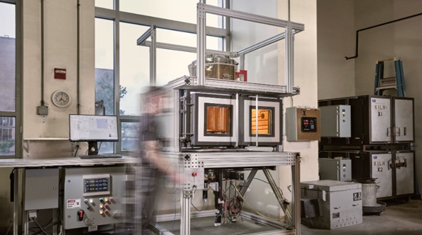
As with all manufacturing applied sciences, compatibility and course of tuning for particular supplies is a needed hurdle to viability. Completely different glass formulations are tuned to the method for which they’re meant, and our analysis explores the mandatory variations of the state-of-the-art of glass 3D printing to work with recycled window glass made with the float glass course of and bottles as a particular instance of container glass. From right here on all window glass shall be known as float glass and all bottle glass as container glass. This exploration focuses particularly on the temperature-viscosity habits of recycled glass as a major determinant of the useful necessities and compatibility with present molten glass additive manufacturing. For instance, soda lime container glass has a better melting temperature and transitions extra rapidly under the softening level to extend manufacturing throughput (Tooley 1984). In contrast, soda lime studio glass used for artisanal glassblowing and former demonstrations of glass 3D printing (Klein et al. 2015) is formulated for a decrease working temperature and is described as ‘longer’ glass, that means that it has an extended working time earlier than it cools to under the softening level. To adapt to a bigger array of glass formulations, the latest glass printer developed by Evenline Inc., the Glass 3D Printer 3 (G3DP3), has been upgraded from its predecessor G3DP2 (Inamura et al. 2018) to prepared the know-how for industrial use. The upgrades made to G3DP3 for printing with recycled float and container glass embrace the incorporation of infrared (IR) temperature monitoring, bigger construct quantity, redesigned nozzle, larger temperature operation, and enhanced software pathing capabilities and prediction. Evenline presently makes use of the G3DP3 know-how for inner manufacturing of each artwork and design objects, to manufacture customized elements for purchasers and to conduct analysis with partnering organizations.
1.3. Additive Manufacturing with Recycled Glass
In parallel to software program and {hardware} upgrades of G3DP3 for printing recycled glass, this work outlines a course of and methodology to grasp the circulation habits of glass and account for modifications essential to print with these untested glasses. We characterize the sensitivity of the additive course of to glass composition, discussing the fabric preparation, and introduce a framework for tuning printing parameters to the temperature-viscosity profile of a given glass formulation. This materials and course of characterization allowed us to display industrial manufacturing of residence items, structural masonry, and sculptural work. These demonstrations include objects which might be totally printed with recycled glass, in addition to a building hybrid the place recycled float glass is printed straight onto a sheet of float glass. By establishing processing parameters for additive manufacturing with recycled glass, and a way of calibrating additive manufacturing throughout a number of glass formulations, we expandthe design house for sustainable and round glass fabrication.
2. Glass Characterization for Printing Calibration
To allow printing of recycled float and container glass, the glass composition was measured and carried out in a mannequin to foretell the viscosity-temperature relationship. The float glass characterised on this work was Optifloat from Pilkington, and the container glass, known as Sapphire, was sourced from a recycling middle in New Orleans. These have been in comparison with 4 varieties of studio glass beforehand examined on the printer, listed in Desk 1. Float and container glass are recognized to have a better melting temperature than that of soda lime studio glasses, that are formulated for guide glassblowing. From the viscosity-temperature relationship, course of parameters have been chosen for an preliminary printing calibration. In the course of the printing course of, the thermal profile and circulation of the glass have been monitored with a thermal digital camera. These have been in comparison with the ensuing mass versus the expected mass of the printed types to check the relative extrusion charges. Particulars of every of the characterization and calibration steps described above are defined within the part under.
2.1. Materials Characterizations
A JEOL JXA-8200 Superprobeelectron-probe microanalyzer (EPMA) or Electron Microprobe was used to measure the chemical composition of 5 completely different formulations of soda lime glass, the outcomes of that are proven in Desk 1. This measurement is restricted by its incapacity to precisely measure components lighter than Oxygen. Of those, Lithium, Boron, and Oxygen are recognized for use in glass formulations to manage numerous properties (Tooley 1984). To keep away from discrepancies between the E-Probe outcomes and the precise glass formulation, security information sheets and product specification sheets have been in comparison with experimental outcomes, and we assumed the addition of Lithium Oxide to the formulation. Following this course of, we normalized the adjusted whole experimental composition to equal 100%.
Desk 1: Elemental composition of 3D printed Studio Glass Compositions and Recycled Industrial Glass Compositions. *Optifloat Chemical Composition was offered by Pilkington **Lithium Oxide composition estimated.

2.2. Utilizing Composition to create Viscosity Comparability of Glass Our bodies
The Vogel-Fulcher-Tammann (VFT) equation can be utilized to mannequin the connection between temperature and viscosity for a variety of glasses. Although broadly used, the mannequin is thought to lose accuracy under annealing temperatures the place it systematically overestimates (Musgraves, Hu, and Calvez 2019).

As a result of important expense wanted to conduct the required experiments to measure viscosities at particular temperatures, composition-based fashions could also be used as an alternative. One broadly utilized and publicly accessible fashions was developed by Fluegel (2007), through which statistical correlations have been developed from viscosities of 2200 experimental glass melts. This mannequin was chosen as a result of it may be utilized to a big selection of glass chemistries. This mannequin is constructed on information from industrial glasses and, because of this, few studio glasses are examined.
Desk 2: VFT constants for the studied glasses.

Sure components exceed the mannequin limits, producing a warning within the Fluegel mannequin. These occurred for the Sapphire, Spruce Pine 87, Bomma, and Optifloat glasses. The weather that set off these limits are reported in Desk 2. These components have been included within the following evaluation however, to grasp the magnitude of their results on the viscosity, a comparability between the efficiency when they’re included in addition to excluded. The outcomes confirmed lower than two levels Celsius distinction throughout a viscosity vary of log 1.5-13.5 Pa-s.
Desk 3: Predicted temperatures at particular viscosities.

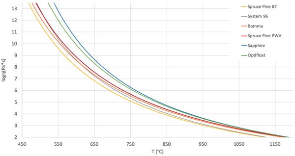
One of many major conclusions that we draw from that is that the 2 industrial glasses, Sapphire and Optifloat, require larger working temperatures to attain the identical viscosities because the studio glasses. We’ve got observed that the working vary for every glass, which we outline because the area or temperature differential between the Working Level and Softening Level, was comparatively constant. The typical vary is 295 °C and the distinction between the biggest and smallest vary is just 24°C. This consistency throughout these completely different glass formulations seems to assist with the power to attain constant outcomes with glass printing throughout a number of glass compositions.
Utilizing the information above in Desk 3 and Fig. 2, the brand new printing parameters appropriate for printing with a beforehand untested glass might be estimated by mapping the equal viscosity of a brand new glass to these of beforehand examined and calibrated glass compositions. The VFT equation is used for this “Viscosity Matching”, setting the right-hand facet of the VFT equation for 2 completely different glass our bodies equal to the identical viscosity and due to this fact additionally one another, as proven under. If the entire VFT constants and an enter temperature for one glass are recognized, the corresponding equal viscosity temperature of the opposite glass might be calculated.

New print parameters might be derived primarily based on the habits of recognized benchmark glass compositions. This was primarily measured by way of two parameters: the item weight and the extrusion temperature. The management setpoints on G3DP3 are monitored with a thermocouple and the extrusion temperature of the glass is measured with an IR digital camera as described under.
2.3. Thermal Imaging, Temperature Measurement, Viscosity Matching
Thermal imagery was captured with an Optris PI 640i G7 thermal digital camera working at 7.9 μm with an assumed emissivity of 0.98. This digital camera is especially nicely fitted to measuring the habits of molten glasses as a result of the emissivity of most glasses stays very near unity over a variety of temperatures. This supplies two essential advantages: the emissivity doesn’t should be adjusted primarily based on the goal temperature and the glass physique acts as an almost black physique enabling the disregard of excessive or low temperature reflections that in any other case tremendously affect measurement (Thompson et al. 2021)(Optris GmbH, n.d.).
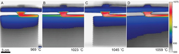
Brief movies of glass printing have been taken through the printing of objects. The utmost temperature from video frames and recorded. Determine 3 exhibits the temperature recorded through the printing of 1 with every of 4 glasses used within the G3DP3 system with thermal monitoring.
Desk 4: Fabrication particulars for pattern objected studied with thermography.

Evaluating the corresponding experimental weights from check objects to the software-predicted weight of every object offered further perception into the viscosity throughout every print. The set temperature for the print was chosen primarily based on the mannequin described in Part 2.2 and the variations from predicted mass (listed in Desk 3) offered further perception into how a lot the temperature ought to be adjusted for future manufacturing.
For the event of course of parameters for Optifloat, it was potential to make the most of the beforehand profitable setpoints to foretell a goal circulation temperature for this new glass. Particularly, the measurement of an extrusion temperature of 1023°C for Spruce Pine PWV was translated to an equal set level of 1037°C in Optifloat utilizing Equation 3 and the constants proven in Desk 2. Given the quite a few sources of error that influence this calculation, it’s anticipated that variations shall be noticed throughout operation of the G3DP3 system and the noticed mass error of three.2% is comparatively small. This research of a number of glass compositions and implementation of thermography has led to a higher understanding of how glass flows by way of the G3DP3 and shortened the calibration time for printing with new glass formulations.
3. Processing Container and Float Glass for 3D Printing
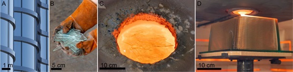
The container or container glass for this undertaking was sourced from a recycling firm, Glass Half Full(New Orleans, LA). Particularly the product was a Bombay Blue L1 glass cullet, referred to on this paper as Sapphire glass. The containers have been damaged all the way down to a median particle diameter of three.5mm. The glass was melted in a JenKen AFG Double Wall Crucible Kiln, at 119oC. The kiln was crammed withapproximate 10 kg batches of cullet preheated to 621oC in an oven. A batch was added each 1.5 hoursto permit the system to equalize to the set temperature. As soon as full, the kiln was held at 1190oC for 12 hours of conditioning, after which the glass was gathered (pulled from the kiln utilizing a gathering ball)and loaded into G3DP3 to print.
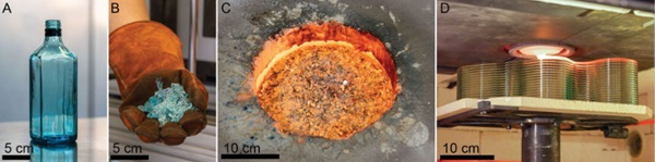
Postconsumer float glass within the type of home windows might be taken from deconstructed buildings, damaged auto glass, and industrial glazing waste amongst different sources. For these experiments, to keep away from any alternatives for contamination, we used Optifloat float glass offered straight by Pilkington. The glass was crushed with a hammer and the ensuing cullet was 12 cm alongside its largest dimension. The identical process for filling the JenKen kiln with container glass was used with the exception that the kiln temperature was set to 1218 oC.
4. Printing with Recycled Industrial Glasses
4.1. Validating New Glasses for Additive Manufacturing
The viscosity matching method described in Part 2 was used to foretell an preliminary set level for the printer extrusion temperature. In parallel, a check soften was produced within the JenKen kiln and a glass rod was manually shaped. Utilizing this glass rod, a easy bend check was carried out within the annealing ovens and a median was taken following studio glass ideas outlined by Henry Halem (2006).
Temperature set factors for the melting furnace, nozzle furnace and print chamber have been chosen for every glass to supply an output circulation on the predicted viscosity set level. As soon as the machine was working, the management temperatures have been adjusted to get the output circulation to an acceptable vary, as monitored by the thermal digital camera.
After full objects have been totally printed, their weights have been in contrast with the expected weights and the management temperatures have been additional adjusted to optimize settings. One of many check objects that was printed out of every glass was Materials Ticks, an artwork sequence that appears on the dynamic response of programmed deviations from the trail of a flat wall resulting in glass drips (Fig. 6). The drip sizing supplies a visually compelling artifact that exhibits viscosity frozen in time, enabling a visible comparability of the mobility of the glass on the given temperature settings.
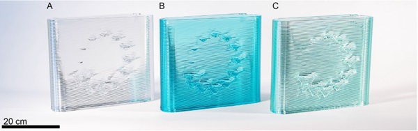
We initially hypothesized that the variations in glass composition (that are simply perceived when manually forming the glass) would equally be mapped visually into every of the printed glass artifacts. As a substitute, a outstanding consistency of the glass drips between supplies was noticed. Two major conclusions have been drawn from this set of experiments. First, the printer can very successfully be recalibrated for various glass formulations; Second, with constant settings in a viscosity house (viscosity matching), the ensuing outputs of the printer are remarkably related.
4.2. Printing on sheet glass
The usage of float glass opens the design house of printing straight onto a sheet of float glass, due to their matched materials and coefficient of thermal growth qualities. Matching thermal expansions throughout completely different glasses is a difficult job and a poor match reduces the energy of the bondsbetween the 2 (Seel et al. 2018). On this research, Optifloat was used, however these similar ideas apply to different float glasses as nicely. The added thickness of the sheet glass was programmed into the system and chosen earlier than every print. Profitable prints have been achieved on 3.2, 6.4, 9.5 mm sheets of glass. The glass sheets have been preheated on the G3DP3 commonplace ceramic construct plate to simply above their annealing temperature to stabilize the glass for loading into the glass printer. The standard printing course of was then run with the addition of a vertical offset from the construct plate to account for sheet glass thickness.
This strategy to fabrication can rapidly produce 2.5D constructions, usually known as rib on plate constructions. This geometry is used often for comparatively light-weight however stiff constructions as in comparison with stable slabs of the identical supplies. These are discovered broadly in aerospace and in telescope mirrors (Zirker 2005)and in architectural purposes of huge glass panels that require stiffening (Pfarr and Louter 2023). The feasibility of printing on glass was manually demonstrated by (Seel et al. 2018) and the power to print glass on sheets opens an area the place the construction is clear but in addition seen, presenting a possibility to combine it as an architectural design component.
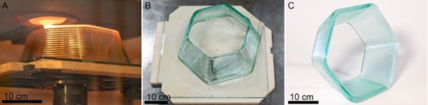
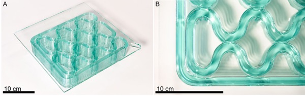
As a part of this preliminary exploration, two designs have been examined. The primary was a tapered hexagonal extrusion, (proven in Figs. 7 & 8). This check object offered a possibility to validate this methodology with an easy design that may later be tessellated, whereas calibration of the interplay of the printed materials with the sheet glass served as the main target of this experiment.
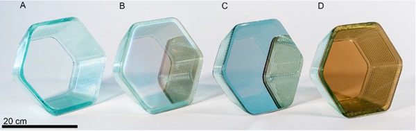
Along with printing on a sheet of the identical Pilkington Optifloat that was used as feedstock, experiments have been carried out on completely different Pilkington merchandise with an array of excessive temperature coatings, the outcomes of that are proven in Determine 8.
The second design examined, a rib on plate construction, was a mobile fill optimized for the glass printer and modeled after the glass-thermoplastic composite generated by Pfarr and Louter (2023). The shape, proven in Determine 9, is characterised by mild curvatures and set as much as generate fusion between adjoining beads of glass. The success of each varieties of printing give confidence that with this technique, the remelted and printed glass remains to be nicely matched from a thermal growth perspective with the uncooked sheet glass. It was noticed that any ceramic particles on the construct plate would grow to be embedded within the sheet. For the reason that sheets are already at their annealing temperature, depositing excessive temperature glass on the floor heats the underside layer of the sheet sufficient to distort it. It’s anticipated that transitioning to a construct plate with a distinct materials could cut back or remove this impact.
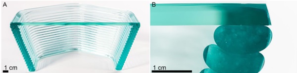
Earlier than implementing this at a bigger scale, structural checks are required to characterize the energy of the bond between the primary layer and the sheet glass plate. A cross-section of the preheated plate glass to molten printed glass bond and interface between printed beads is seen in Determine 10.
5. Dialogue
This work efficiently demonstrates G3DP3 can be utilized to additively manufacture a variety of various objects out of various glass formulations. These glasses have a better melting level and distinct attribute habits from the glass formulations beforehand printed. Moreover, now we have demonstrated a workflow for adjusting printing parameters to accommodate new glass formulations in 3DGP3. The main target of this analysis was to check the feasibility of printing recycled soda lime glass from two predominant streams, float glass and container glass. The authors consider that, given the similarity of float and container glasses, these outcomes can be utilized to print from different sources of glass. Future work may contain collaboration with glass recycling facilities to find out 3DGP3’s sensitivity to put up shopper contamination. Characterizing or enhancing the printing course of to be much less delicate to materials variation may relieve stress in upstream sorting and cleansing previous to printing the glass into new merchandise or building supplies.
Primarily based on this analysis, just a few variants of the subsequent technology molten glass 3D printer, G3DP4, may succeed Evenline’s G3DP3. For instance, the facet ratio of the construct chamber may very well be modified to generate a big space, low top model designed for printing on massive sheets of float glass for giant scale architectural facade growth. The dimensions of the mobile fill sample printed on Optifloat (Fig. 9)is smaller than what may very well be carried out with earlier technology of the printer and highlights progress in each the fabric and a particular class of geometries that may be 3D printed in optically clear glass. We hope to pursue a undertaking that makes use of G3DP4 to print on a lot bigger sheets of glass. One other variant could embrace additional growth of the molten glass printer’s working temperatures to 1700 oC to permit for the printing of glass with larger melting temperature, similar to borosilicate, silica, and even lunar regolith.
Acknowledgements
We thank the Rochester Institute of Know-how’s School of Artwork and Design for supporting Evenline’s analysis in molten glass 3D printing. Particularly, Todd Jokl, Suzanne Peck, David Schnukel, Brendan Miller and Will Tracy have been instrumental on this effort. We need to thank Raphael Abel for his design work, assist with recycling and operation of the printer. We additionally thank Kyle Sword, Shona Taylor and the remainder of the staff at Pilkington Glass North America, a part of Nippon Sheet Glass Firm, Ltd (NSG). We thank Priscilla Lo and Bella Walters for help working the glass printer and chilly working, in addition to Mackenzie Serwa for her pictures. Lastly, we thank the staff at Glass Half Full, Greg Fiddler from Spruce Pine Batch, and Tony Marino from AGI. Composition measurements have been carried out on the MIT Electron Microprobe Facility.
References
Dhir, Ravindra Okay., and College of Dundee, eds. 2001. Recycling and Reuse of Glass Cullet: Proceedings of the Worldwide Symposium, Organised by the Concrete Know-how Unit and Held on the College of Dundee, Scotland, UK on 19 – 20 March 2001. London: Telford.
Fluegel, Alexander. 2007. “Glass Viscosity Calculation Primarily based on a World Statistical Modelling Method.” Glass Know-how 48 (1).
Halem, Henry. 2006. Glass Notes, a Reference for the Glass Artist. 4th version. Franklin Mills Pr.
Inamura, Chikara, Michael Stern, Daniel Lizardo, Peter Houk, and Neri Oxman. 2018. “Additive Manufacturing of Clear Glass Constructions.” 3D Printing and Additive Manufacturing 5 (4): 269–83. https://doi.org/10.1089/3dp.2018.0157.
Jordan, John M. 2018. 3D Printing. The MIT Press Important Information Collection. Cambridge, Massachusetts London, England: The MIT Press.
Klein, John, Michael Stern, Giorgia Franchin, Markus Kayser, Chikara Inamura, Shreya Dave, James C. Weaver, et al. 2015. “Additive Manufacturing of Optically Clear Glass.” 3D Printing and Additive Manufacturing 2 (3): 92–105. https://doi.org/10.1089/3dp.2015.0021.
Oikonomopoulou, Ivneet Singh Bhatia, Wilfried Damen, Felix Van Der Weijst, and Telesilla Bristogianni. 2020. “Rethinking the Solid Glass Mould.” Difficult Glass Convention Proceedings, September, Vol. 7 (2020): Difficult Glass 7. https://doi.org/10.7480/CGC.7.4662.
Optris GmbH. n.d. “Non-Contact Temperature Measurement Glass Trade.” Accessed March 2, 2024. https://www.optris.com/en/obtain/glass-industry-brochure/?wpdmdl=160688&refresh=65da90dc0e37c1708822748.
Pfarr, Daniel, and Christian Louter. 2023. “Prototyping of Digitally Manufactured Skinny Glass Composite Façade Panels.” Structure, Constructions and Building 3 (2): 263–73. https://doi.org/10.1007/s44150-022-00080-7.
Seel, M., R. Akerboom, U. Knaack, M. Oechsner, P. Hof, and J. Schneider. 2018. “Fused Glass Deposition Modelling for Purposes within the Constructed Setting: Schmelzschichten Aus Glas Für Anwendungen Im Bauwesen.” Materialwissenschaft Und Werkstofftechnik 49 (7): 870–80. https://doi.org/10.1002/mawe.201800075.
Thompson, James O., Daniel B. Williams, Rachel J. Lee, and Michael S. Ramsey. 2021. “Quantitative Thermal Emission Spectroscopy at Excessive Temperatures: A Laboratory Method for Measurement and Calibration.” Journal of Geophysical Analysis: Stable Earth 126 (7): e2021JB022157. https://doi.org/10.1029/2021JB022157.
Tooley, Fay V. 1984. The Handbook of Glass Manufacture. third ed. Vol. 1. 2 vols. Books for the Glass Trade Division Ashlee Publishing Co., Inc.
Zirker, Jack B. 2005. An Acre of Glass: A Historical past and Forecast of the Telescope. Baltimore: Johns Hopkins college press.